
- Step 1: Install CPU, RAM and M.2 SSD on the motherboard (do this outside the case for easier operation)
- Mount the CPULift the retention lever and open the metal cover of the CPU socket. Align the triangular marker on the CPU with the triangle mark on the socket. Place the CPU gently into position — do not press down. Close the metal cover and push down the retention lever to lock the CPU.
Intel: Contact points are on the motherboard. AMD: Pins are on the CPU. Be careful not to bend any pins.
- Fit the CPU coolerInstall the cooler mounting brackets onto the motherboard. Peel off the protective film on the cooler base. Apply a thin layer of thermal paste (skip this if thermal paste is pre applied on your stock cooler). Align the cooler over the CPU and fasten the clips alternately on both sides. Plug the cooler fan cable into the CPU_FAN header on the motherboard.
- Install RAM modulesPush open the clips at both ends of the memory slot. Line up the notch on the RAM stick with the ridge inside the slot. Press firmly straight down until both side clips click into place.
For two RAM sticks: Use slots 2 and 4 (counting from the CPU) to enable dual channel mode.
- Install M.2 SSDRemove the screw and take off the M.2 heat sink. Insert the SSD at a slight angle into the M.2 slot, lay it flat, then fasten the retention screw. Re attach the heat sink. Step 2: Fit the motherboard into the case
- Remove the side panel of the case. Install stand off screws matching the motherboard mounting holes. Remove any extra stand offs to avoid short circuiting the board.
- Fit the rear I/O shield into the case first. Lower the motherboard into the chassis and line it up with the shield.
- Fasten the motherboard mounting screws (do not over tighten).
Step 3: Install the Power Supply Unit (PSU)
Available form factors: ATX (full size), SFX (small form).
- Slide the PSU into the PSU compartment. Fan orientation: fan faces down for bottom mount cases; fan faces up for top mount cases. Secure with screws.
- Connect main power cables:
- 24 pin main motherboard power: The largest connector, plug into the 24 pin socket on the motherboard.
- CPU power 4+4 / 8 pin: Near the CPU socket. This must be connected.
Step 4: Install the graphics card
- Remove the corresponding metal slot brackets from the back of the case.
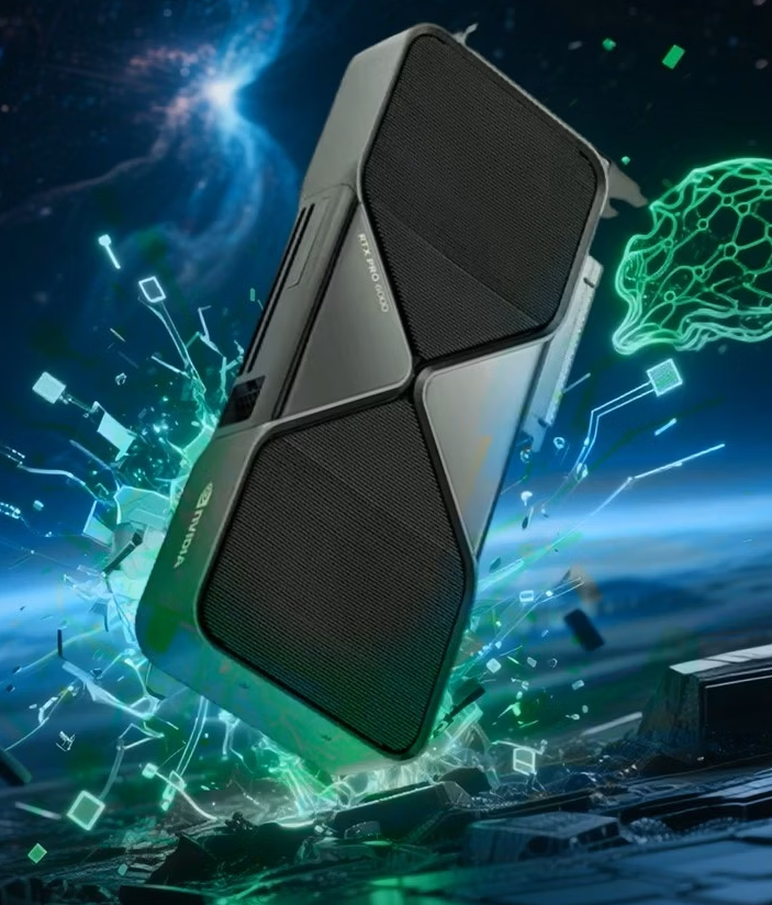
- Align the gold finger edge of the GPU with the PCIe x16 slot on the motherboard. Press straight down until the slot latch clicks. Screw the GPU bracket to the case.
- Attach GPU power cables (6 pin / 8 pin). High end cards require multiple power connectors — plug all of them in.
Skip this step if you use CPU integrated graphics.
Step 5: Front panel and fan wiring
Front panel cables: Power SW, Reset SW, Power LED, HDD LED, USB ports, audio header.
- Power SW (Power switch): No polarity, works either way.
- Reset SW (Reset switch): No polarity.
- LED indicators (Power LED, HDD LED): Observe polarity. White wire = negative, colored wire = positive. Reversed LEDs will not light up but cause no damage.
- Plug in the large blue USB 3.0 header and HD Audio header to the matching motherboard pins.
- Case fans connect to SYS_FAN Do not plug case fans into CPU_FAN.
Step 6: Final check and first power on
- Double check all connections: 24 pin, CPU power, GPU power, all latches locked. Make sure no loose screws are left inside the case.
- Connect your monitor cable to the graphics card port, NOT the motherboard port when a discrete GPU is installed.
- Plug in the power cord and press the case power button.
- Fans spin and monitor enters BIOS → hardware assembly completed.
- No display: Re seat RAM and graphics card, double check power connections.
Step 7: BIOS setup & Operating System installation
- Press Delor F2 on boot to enter BIOS. Verify CPU, memory and storage are detected. Enable XMP for memory speed.
- Create a Windows installation USB drive. Boot from the USB and install Windows.
- After entering Windows, install chipset and graphics drivers.
Common beginner mistakes
- Never force connectors. If it will not fit, you have the wrong orientation.
- With discrete GPU, monitor cable must connect to video outputs on the graphics card, not motherboard.
- Missing CPU power cable is a frequent cause of no boot.
- Confirm M.2 SSD protocol (NVMe / SATA) matches motherboard support.
- Misplaced stand off screws can cause short circuits and hardware damage.